[mathjax]
Huygens’ Principle
In order to understand why there is the optimum value for a pinhole diameter, we consider the mechanism of the pinhole phenomenon by using a simple model. We analyze the problem on the basis of the famous Huygens’ principle (1690, Holland, Christiaan Huygens, 1629 -1695). It should be noted that, as by the original Huygens’ principle the diffraction phenomenon of a light wave cannot be explained properly, the principle of Huygens and Fresnel is used for the analysis as the “Huygens’ Principle”, where the effect of the interference is taken into account appropriately.
According to the Huygens’ principle, secondary spherical waves are emitted from points on the surface wavefront of an incident light wave and the envelop of the secondary spherical waves form a new surface wavefront (figure below). Therefore, a light wave with a flat surface (a plane wave) remains a plane wave without change in every point endlessly.
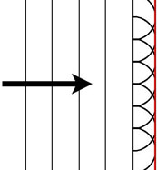
Huygens’ principle
A new surface wavefront is formed by an envelope (a red line) of secondary spherical waves each of which is emitted from a point on a previous surface wavefront as a source.
According to the Huygens’ principle, secondary spherical waves are emitted from points on a surface wavefront of an incident light wave and the envelop of the secondary waves form a new surface wavefront (above figure). Therefore, a light wave with a flat surface (a plane wave) remains a plane wave without change in every point.
However, when the plane wave encounters a wall with a very small pinhole, a new secondary spherical wave is emitted from the pinhole as a point source (figure below). The new wavefront is that of the secondary wave itself because the pinhole is very small and the source is considered mathematically as a point without an area. By applying the Huygens’ principle to this spherical wave, it is understandable that the light wave after passing through the pinhole remains still a spherical wave in every point. In this case the ”pinhole phenomenon“ cannot be observed because the light wave does not go straight to the traveling direction of the incident plane wave.
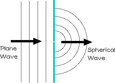 Small pinhole case
When a diameter of a pinhole is extremely small a light of a plane wave passing through the pinhole becomes a spherical wave.
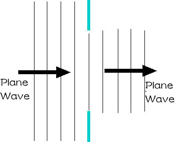 Large pinhole case
When a diameter of a pinhole is very large a light of a plane wave passing through the pinhole remains a plane wave.
Smallness of a Pinhole
Then, how small is a diameter of an extremely small pinhole? We consider the length on the basis of the wave length of the visible light wave, i.e., \(400 – 700 nm\) (\(1 nm = 1/1000000 mm\)). This gives a criterion whether the light wave after passing through a pinhole becomes a spherical wave or a plane wave. However, the distance between a pinhole and an imaging screen is also important when we consider if the image on the screen will blur after passing through the pinhole due to the diffraction phenomenon. When we use a pinhole camera with this distance of \(50 mm\) the effect of the diffraction phenomenon will be observed for a pinhole with the diameter of \(0.1 mm\) (\(=100,000 nm\)). This length is 200 times as large as wavelength of visible light. It should be remarked that even a pinhole with such a “large diameter” is an extremely small pinhole!! If a diameter of a pinhole is very large in comparison with the wavelength of light, a plane wave of light entering the pinhole proceeds rectilinearly as a plane wave after passing through the pinhole. You may be disinclined against the fact that a light ray with a diameter of, for example, \(0.3 mm\) is a plane wave, but this length is about 1000 times as large as wavelength of the visible light and the light ray is surely a plane wave.
Behavior of a Diffracted Light Wave
It may be instructive to display the dependence of the behavior of the light beam passing through a pinhole on its size. We consider the behavior of a light wave with a wavelength \(\lambda\) of \(550 nm\) emitted from a point source at infinity. For simplicity we assume that the light wave passes through a slit instead of a pinhole and calculate the wave propagation on the basis of the Fresnel diffraction. Contour plots of intensity distribution (white: high intensity, black: low intensity) of the light for cases of different slit widths, \(d=0.05, 0.1, 0.15\), and \(0.3 mm\) are shown in the following figure. Pink bands denote paths of the light wave when the diffraction is not taken into account. Though both the units of the vertical and the horizontal axes are millimeters in this figure, it should be noted that the horizontal axis is extremely expanded. Because the effect of the diffraction is more noticeable in the distance from the pinhole plate and in the case of small pinhole, an image projected on a distant screen becomes more sharper with increasing width of the slit.
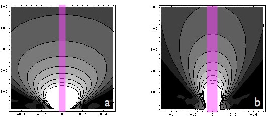
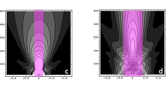
Dependence of diffracted light intensity on pinhole size (slit width)
In this figure a slit is located on the horizontal axis and the incident light comes from beneath. The pink band denotes the light beam without the diffraction phenomenon. Sub-figures (a), (b), (c), and (d) show the cases with the slit width \(d=0.05, 0.1, 0.15\), and \(0.3 mm\), respectively.
From the above figure it is not difficult to understand that the diffracted light diverges rapidly in the case of a narrow slit as \(d=0.05 mm\) but by using a wider slit as \(d=0.15 mm\) the width of the light beam is confined within the width of the slit at the distance of \(100 mm\) from the pinhole plane. We made calculation of the distribution of the light intensity at the focal plane for the case of the slit width of \(d=0.15mm\) (figure below). It is also clearly seen that the minimum beam width is attained for \(d=0.15 mm\).
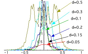 Distribution of the light intensity on the imaging plane (f=100 mm) for different slit widths, \(d=0.05, 0.1, 0.15\), and \(0.3 mm\).
Optimum diameter of a pinhole
This equation is the same one as that in the main text. There are more other formulas with different coefficient. But differences are not important. It is important that the diameter of the pinhole is proportional to \(\sqrt{\lambda}$$/. As there are a certain finite extent of the range of wavelength of the visible light the optimum value of diameter of a pinhole becomes different for different choice of wavelength. But such a difference is not an obstacle to take a photograph.
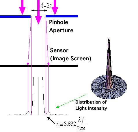 Determination of the optimum pinhole diameter
Determine the pinhole diameter from the diameter of the central circle of the distribution of the light diffracted by a circular pinhole.